

تخيل أرضية مصنع صناعي ضخم مملوء بأحزمة نقل ثقيلة ومضخات تبريد آلية. يؤدي تشغيل هذه المحركات الكهربائية الضخمة من نقطة توقف مسدودة إلى خلق ضغط كهربائي هائل عبر شبكة الطاقة لديك.
بسبب الفيزياء الأساسية, تتطلب ملفات المحركات الثابتة الضخمة كميات لا تصدق من الطاقة الكهربائية الأولية. هذا المفاجئ, يمكن للطلب الكهربائي العنيف أن يؤدي بسهولة إلى تعطيل قواطع دوائر السلامة وإتلاف أنظمة التحكم الدقيقة.
لذلك, يجب على مهندسي أتمتة المصانع إدارة هذه الارتفاعات العملاقة في الطاقة بعناية فائقة ودقة. يقومون في كثير من الأحيان بتركيب عاكس ثلاثي الطور للخدمة الشاقة للتحكم في توصيل الجهد الكهربي الوارد بأمان.
يسلط هذا الدليل الفني الضوء على كيفية تخفيف إلكترونيات الطاقة الحديثة لتيارات التدفق الحثية الخطيرة أثناء بدء التشغيل. سوف نستكشف أسرار تعديل عرض النبضة, أنظمة الحد الحالية الديناميكية, وممارسات الأتمتة الصناعية الذكية.
الفيزياء العنيفة وراء طفرات اندفاع المحركات الصناعية
هل سبق لك أن تساءلت عن سبب وميض أضواء المصانع عندما تبدأ الآلات الصناعية الثقيلة في العمل فجأة؟? عندما يستقر المحرك التعريفي عند سرعة صفر, أنها تمتلك صفرًا من القوة الدافعة الكهربائية الداخلية.
بالتالي, يؤدي توصيل طاقة الشبكة الخام مباشرة بالمحرك إلى إنشاء دائرة كهربائية قصيرة مؤقتة. يرتفع التيار الكهربائي الوارد على الفور إلى ستة أو ثمانية أضعاف مقاييس التشغيل العادية.
[Direct Grid Startup] ---> Zero Counter-EMF Spikes ---> Giant Current Surge ---> Tripped Breakers
[Inverter Control]    ---> Controlled Frequency ---> Soft Smooth Ramp Up ---> Stable Power Grid
لمواجهة هذا الارتفاع الحالي الهائل, يجب على الفرق الهندسية أن تتخلى تمامًا عن المبتدئين المغناطيسيين في المدرسة القديمة. يؤدي استخدام نظام التحكم الذكي في الحالة الصلبة إلى تغيير معلمات توصيل الطاقة الواردة مباشرة من المصدر.
هذا النهج الحديث يزيل العواصف الكهربائية العنيفة, إنقاذ معدات المصنع الخاصة بك من التآكل الميكانيكي المبكر. يعمل استقرار الطاقة هذا على حماية أجهزتك باهظة الثمن, ضمان تشغيل خطوط التجميع الآلية بسلاسة طوال اليوم.

سلاسة توصيل الطاقة عبر إعدادات محرك التردد المتغير المتطورة
لا تمنحك أجهزة التشغيل القياسية عبر الخط أي تحكم في كيفية تدفق الكهرباء إلى أجهزتك أثناء بدء التشغيل. لكن, يتيح لك ضبط إعدادات محرك التردد المتغير الداخلي تخصيص منحنى بدء التشغيل بالكامل.
تعمل وحدات الطاقة الحديثة على تغيير كل من خرج الجهد وتردد التشغيل في وقت واحد باستخدام المعالجات الدقيقة الذكية. تحافظ آلية التحكم الدقيقة هذه على توازن الحقول المغناطيسية الداخلية بشكل مثالي داخل قلب المحرك الدوار.
[Adjustable Acceleration Ramps] ---> Gradual Frequency Step-Up ---> Controls Magnetizing Current
[Voltage-to-Frequency Scaling]  ---> Constant Torque Profiles ---> Eliminates High Current Spikes
لأن محرك الأقراص يرتفع طاقته تدريجيًا, يتسارع المحرك بسلاسة دون الحاجة إلى دفعات عملاقة من الكهرباء. تقوم ترانزستورات الطاقة الداخلية بتعديل تدفق الطاقة بشكل مستمر, مطابقة متطلبات الحمل المادي الدقيقة الخاصة بك بشكل مثالي.
| طريقة بدء تشغيل المحرك | الأولي الذروة الحالية | خطر الصدمة الميكانيكية | إجمالي إجهاد طاقة الشبكة |
| مباشر اون لاين (دول) | 600% ل 800% تصنيف | عالية بشكل استثنائي | انخفاض حاد في جهد الشبكة |
| ستار دلتا ستارتر | 300% ل 400% تصنيف | ارتفاع عابر مرتفع | الإجهاد التشغيلي المعتدل |
| عاكس الحالة الصلبة | 100% ل 150% تصنيف | الصفر على الاطلاق | الحد الأدنى لسحب الحمل السلس |
التخفيف الديناميكي من خلال التحكم المتقدم في محرك التشغيل الناعم
يتطلب طول عمر النظام الكهربائي الحقيقي مراقبة كيفية تطور المجالات المغناطيسية داخل ملفات المحرك أثناء بدء التشغيل. إذا قمت بتطبيق القوة بزاوية رياضية خاطئة, تواجه مكوناتك الداخلية ضغطًا حراريًا شديدًا.
نشر الأمثل التحكم في تشغيل المحرك الناعم تسمح الإجراءات الروتينية للمحرك بتتبع مواقع الدوار في الوقت الفعلي. يستخدم برنامج التحكم الداخلي خوارزميات رياضية سريعة لضبط خرج الجهد آلاف المرات في الثانية.
بالإضافة إلى, يمنع هذا التتبع الآلي السريع حلقات التيار الداخلية من تجاوز عتبات التشغيل الآمن المحددة مسبقًا. يقوم محرك الأقراص بتقييد إنتاج الطاقة بشكل فعال, حماية مفاتيحها الداخلية المصنوعة من السيليكون من التحول إلى خردة معدنية قابلة للصهر.
-
كشف تدفق الكبح: يمنع ردود فعل جهد التجديد الخطيرة من تدمير مكثفات الحافلة الداخلية.
-
منحنيات S قابلة للبرمجة: يعمل على تنعيم ملفات التسارع الأولية لحماية روابط الحزام الناقل الميكانيكية الدقيقة.
-
اثار زاوية المرحلة: يعمل على تحسين خطوط التدفق الحالية الأولية عبر جميع مراحل الطاقة الثلاث بشكل مثالي.
-
الزائد المجسات الحرارية: مراقبة درجات حرارة الوصلات الداخلية لمنع حدوث إرهاق غير متوقع للأجهزة على الخطوط.
معايرة معلمات وقت التسريع
يتطلب تحقيق الإقلاع الميكانيكي السلس مطابقة وقت منحدر التسارع مع وزن دولاب الموازنة الفعلي. تعرف على المزيد حول ضبط معلمات منحدر تسارع العاكس للتخلص من أخطاء التيار الزائد المزعجة أثناء بدء التشغيل عالي القصور الذاتي.
ترقية الأنظمة من خلال ترقية إلكترونيات الطاقة الصناعية
تتردد العديد من عمليات المصانع التقليدية في استبدال جهات الاتصال الميكانيكية القديمة بمحركات أقراص رقمية معقدة. لكن, تتآكل الموصلات الفيزيائية القديمة بسرعة تحت حرارة الانحناء الشديدة الناجمة عن الزيادات الحثية.
يؤدي تنفيذ ترقية شاملة لإلكترونيات الطاقة الصناعية إلى تقديم ترانزستورات قوية ثنائية القطب ذات بوابة معزولة إلى شبكة الطاقة لديك. تتحكم مفاتيح الحالة الصلبة المتقدمة هذه في كتل ضخمة من الطاقة الكهربائية دون إنتاج أي شرارات مادية.
رؤية الأتمتة الميدانية: تتميز المحولات الذكية الحديثة باختناقات وصلة DC مدمجة. تمتص ملفات الترشيح الداخلية هذه الارتفاعات السريعة في التيار قبل أن تؤدي الضوضاء إلى إتلاف اتصالات المصنع الرقمية.
بالإضافة إلى ذلك, تعمل أنظمة الحالة الصلبة على خفض إجمالي رسوم المرافق الكهربائية في ذروة الطلب في المصنع بشكل كبير. من خلال التخلص من تلك الزيادات العالية الحالية في بدء التشغيل, يمكنك تأمين أسعار طاقة أفضل من مزود المرافق المحلي الخاص بك.

4 خطوات تكوين العاكس الخاص بك للأحمال الثقيلة بأمان
تتطلب إدارة الشركات الناشئة ذات عزم الدوران العالي توخي الحذر, عملية تشغيل منهجية لضمان السلامة المطلقة لخط المصنع.
التغلب على التشبع الحالي وأخطاء التيار الزائد المزعجة
يمثل الحفاظ على تشغيل الأنظمة عالية الطاقة بسلاسة أثناء بدء التشغيل في الصباح البارد صداعًا كبيرًا لكهربائيي المصانع. يزيد الشحم الميكانيكي البارد من مقاومة الدوران الأولية, إجبار محرك الأقراص على العمل بجهد أكبر لتدوير الأعمدة.
لحسن الحظ, تستخدم البرامج الثابتة الحديثة للعاكس حلقات متقدمة للتحكم في المتجهات لإدارة هذا الاحتكاك الميكانيكي الأولي. يتتبع محرك الأقراص الزوايا الحالية على الفور, تحويل الطاقة إلى توليد عزم الدوران مع الحفاظ على إجمالي الأمبيرات منخفضة. اقرأ دليلنا الشامل لاستكشاف الأخطاء وإصلاحها حول إصلاح أخطاء التيار الزائد للعاكس للحفاظ على حركة خطوط الإنتاج لديك.
[Scalar V/Hz Control Loop] ---> Ignores Real-Time Rotor Load ---> Current Spikes and Faults Out
[Active Vector Control]    ---> Measures True Winding Flux  ---> Delivers Exact Torque Smoothly
بالإضافة إلى ذلك, انتبه جيدًا لاختيارك لمقاومات الكبح الداخلية أثناء مراحل تصميم النظام لديك. يسمح تركيب كتل الكبح الديناميكية للخدمة الشاقة للمحرك بالتعامل مع التباطؤ المفاجئ دون التعثر في أخطاء الجهد الزائد.
القيمة الحقيقية للشركات لتقنية محول الطاقة المتميزة
إن ترقية منشأتك الصناعية بشبكات التحكم المتقدمة في الطاقة توفر مزايا مالية هائلة على المدى الطويل لشركات الإنتاج.
أولاً, يعمل التحكم الدقيق في التيار على إطالة العمر التشغيلي الإجمالي للمحركات الكهربائية الخاصة بك عن طريق تقليل الحرارة الداخلية. عندما تتخلص من صدمات بدء التشغيل القاسية, يظل عزل اللف الداخلي الخاص بك جديدًا وموثوقًا لعقود من الزمن. هذه المتانة توفر عليك تكاليف إعادة اللف الباهظة الثمن.
ثانية, يعمل التشغيل السلس للمحرك على التخلص من أحمال الصدمات الميكانيكية الشديدة عبر شبكة قطار الحركة الفعلية بالكامل. علب التروس, سلاسل القيادة, وتدوم أحزمة النقل المطاطية لفترة أطول بكثير عند التخلص من الهزات العنيفة في البداية. تتوقف أجهزة الطاقة الخاصة بك عن كونها صندوق تحكم بسيط وتصبح أحد الأصول الحيوية لربحية المصنع.
قم بحماية شبكة النباتات الخاصة بك باستخدام أنظمة التحكم الحديثة
هل يمكن أن يؤدي تغيير أجهزة بدء تشغيل محرك المصنع إلى تحويل كفاءتك التشغيلية وموثوقية الشبكة حقًا? تؤكد بيانات هندسة الطاقة التجريبية أن الإدارة الحالية للحالة الصلبة تحمي البنية التحتية الخاصة بك بشكل أفضل.
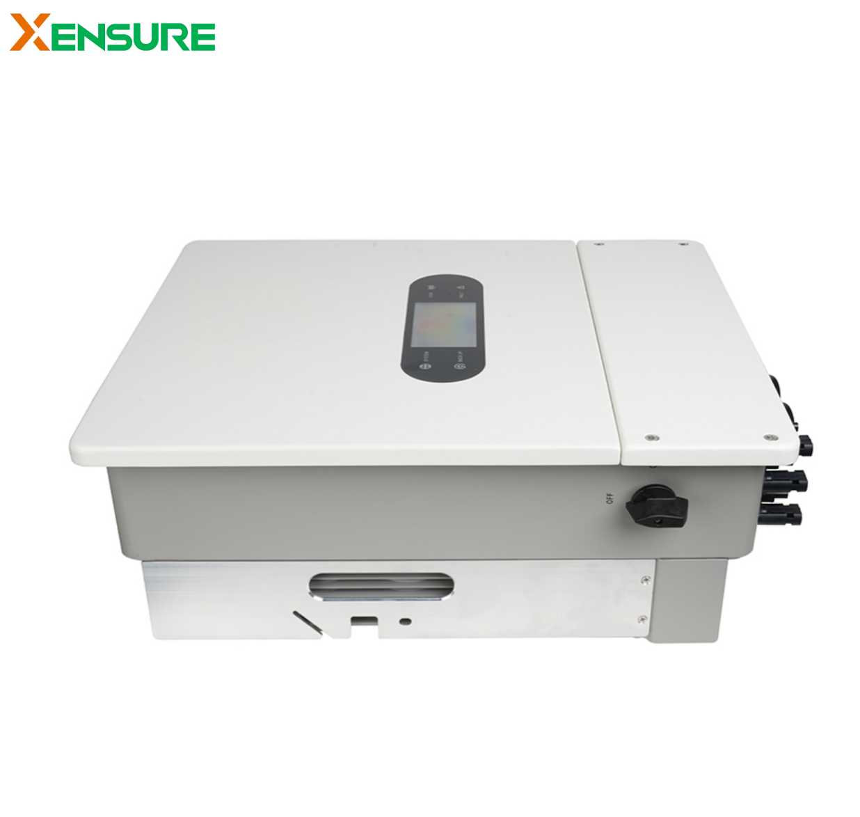
من خلال الابتعاد عن المشغلات الميكانيكية القديمة نحو عاكس متقدم ثلاثي الطور, يمكنك التغلب على التيارات المفاجئة. إن نشر الإعدادات الذكية المصممة للتخلص من تيارات التدفق الحثية يضمن تشغيل أجهزتك بأمان دون الضغط على شبكتك. استثمر في ترقيات إلكترونيات الطاقة عالية الجودة اليوم لحماية معداتك وتبسيط خطوط الإنتاج لديك.